Hey
@ Mhz! soz m8 im to dumb to put that reaction into an equation form ha ha im really not a mathematically minded or scientifically trained person, but here is what happens, maybe you could convert what i write into an equation

The reaction is joining four hydrogen atoms into one helium atom. Two hydrogen atoms (one proton and one electron) join into a heavy hydrogen atom (one proton and neutron with one electron). The extra electron joins with its proton to produce the neutron. This makes the heavy hydrogen atom called deuterium. Two deuterium atoms then fuse into one helium atom. The four hydrogen atoms we started with have greater mass than the one helium atom we end with. The lost mass is released as radioactive energy. All be it only a small amount of mass is lost, multiplying the small mass by the speed of light squared, results in a large amount of energy. Here are some links on the fusor device
http://en.wikipedia.org/wiki/Farnsworth ... rsch_fusor@Nix Nice little setup m8, i to did this with small PM dc printer motors at 12v running them from a bench supply or even an old pc power supply!
your question about the dc output of your motor, it is indeed dc! it works like this, an ac current is produced by the rotation of the armature (Coils) through the opposing magnetic fields of the permanent magnets, thus an ac current is induced, a sine wave, this ac is then passed to the commutator that is made up of copper strips soldered to the ends of each of the windings, these strips are isolated from each other, the commutator spins with the brushes making contact with the commutator segments which switches the current on-off-on-off-on-off, continuously, each on-off is performed over one half cycle of the sine wave (one half rotation of the coil) or twice per cycle, here is a drawing (forgive my crude photoshoping

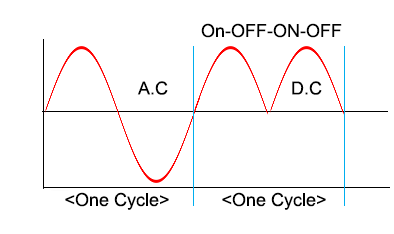
- ac-dc.png (9.66 KiB) Viewed 55903 times
so the latter half of each full sine (Negative) is chopped of leaving a half wave, On a purposly constructed DC generator, many coils switching in this manner around a commutator with many sections, pushes a great many half wave pulses out into a steady usable direct current stream! man im rubbish at explaining things!
an ac generator is constructed virtually the same apart from the means of current collection, its commutator is in the form of solid slip rings that output the full ac waves
ok well what i discovered was the signals don’t sum by the methods you are attempting, (similar to my first efforts) as they are rather different, i.e the frequency of the dc out signal is different to the dc out of the battery or supply! this is due to the interaction of the split ring commutator segments and brushes plus the rotational speed of the armature making up its output freq, also if you are able to look at these two signals (dc batt - dc gen) on a scope they look very different, so what i was told was the two dc signals need to be made the same to be summed as one signal of greater current, this can be done by means of a regulator circuit like a simple buck boost convertor on the output of the gen and input switching circuits ie, switching between stored gen output (capacitive) and battery/supply input!
Your setup! I’m pretty sure your printer motors are 12v dc, and a little bit much for a 9v battery, try getting a hold of an old pc power supply or some decent 12v batteries to do this bud, they are most likely rated at 9 -14.5 volts, 0.5 amp motors, so you want a good current supply to the motor to produce the required torque to turn the generator, what you are getting with the system bogging down is the load being applied to the generator which results in back torque, eddy currents and B fields in the generator that manifest as drag, requiring more torque from the motor to turn the generator and pump out the current! you can test this out by simply attaching say an led or resistor of some sort to the output of your generator whilst it is running open voltage/un-shorted (without gen to motor feedback loop) you will hear the run motor change speed and slow down as this load is applied, when this is happening your drive motor is pulling more current from its source to maintain its own rotation and in turn rotate the generator with a load
so, in the closed loop scenario the output current from the generator is looped back to the drive motor but it is less than the additional current required to run the system with the extra load imposed by the generator, don’t forget that a regenerative system of this nature is put in place to recapture waste energy from a system that is already doing work of some form and already has a load on the motor, a regenerative system would recapture its energy from conversion of waste kinetic energy or capture of energy from the environment whereas this setup costs more than it converts/generates! Since the motors are not 100% efficient there are losses right from the start, the generator is very inefficient and adds greater losses in the form of drag and consumption so you see the catch 22 that many great inventors have tried to overcome!
This drag force from the generators is exactly how regenerative braking works in a car, when you apply the brake it engages 4 generators through gearing, these are connected to the load (batteries) and the resulting back torque slows the car down.
some AC induction motors actually speed up under load which is quite strange! microwave fan motors do this!
so can this be done make an efficient motor gen? Yup but not by doing it with matched dc motor/generators! unless you do this
- Fig112.gif (11.68 KiB) Viewed 55903 times
There are quite a few regenerative motor/gen inventions out there now,
bedini motors (bemf capture from collapsing magnetic field, environmental energy conversion)
cole motors (bemf capture from collapsing magnetic field, environmental energy conversion)
qmogen (amplification, regulation, dc-ac -ac-dc convention, step-up)
Gravity motor/gens
air/gas compressor generators
Tesla turbine
grey motor
And a few solid state contraptions that have no moving parts but create the same effects of a motor and generator using fancy pulse generators and switching and iron core coils etc and are said to output either unity or slightly above unity (more out than in) btw science says you cant have overunity but it has been demonstrated many many times in various types of system
this topic kinda makes me want to get some old toys out again to have a play around again!
